What is Induction Heating and induction heating principle?
2013-07-07 From: uihm Views

induction heating
What is Induction Heating?
Induction heating is the process of heating an electrically conducting object (usually a metal) by electromagnetic induction, where eddy currents (also called Foucault currents) are generated within the metal and resistance leads to Joule heating of the metal.
An induction heater (for any process) consists of an induction coil (or electromagnet), through which a high-frequency alternating current (AC) is passed. Heat may also be generated by magnetic hysteresis losses in materials that have significant relative permeability.
The frequency of AC used depends on the object size, material type, coupling (between the work coil and the object to be heated) and the penetration depth.
High Frequency Induction heating is a process which is used to bond, harden or soften metals or other conductive materials. For many modern manufacturing processes, induction heating offers an attractive combination of speed, consistency and control.
The basic principles of induction heating have been understood and applied to manufacturing since the 1920s. During World War II, the technology developed rapidly to meet urgent wartime requirements for a fast, reliable process to harden metal engine parts. More recently, the focus on lean manufacturing techniques and emphasis on improved quality control have led to a rediscovery of induction technology, along with the development of precisely controlled, all solid state induction power supplies.
What makes this heating method so unique? In the most common heating methods, a torch or open flame is directly applied to the metal part. But with induction heating, heat is actually "induced" within the part itself by circulating electrical currents.
Induction heating relies on the unique characteristics of radio frequency (RF) energy - that portion of the electromagnetic spectrum below infrared and microwave energy. Since heat is transferred to the product via electromagnetic waves, the part never comes into direct contact with any flame, the inductor itself does not get hot , and there is no product contamination. When properly set up, the process becomes very repeatable and controllable.
How Induction Heating Works
How exactly does induction heating work? It helps to have a basic understanding of the principles of electricity. When an alternating electrical current is applied to the primary of a transformer, an alternating magnetic field is created. According to Faraday's Law, if the secondaryof the transformer is located within the magnetic field, an electric current will be induced. 
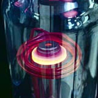
In a basic induction heating setup shown at right, a solid state RF power supply sends an AC current through an inductor (often a copper coil),and the part to be heated (the workpiece) is placed inside the inductor. The inductor serves as the transformer primary and the part to be heated becomes a short circuit secondary. When a metal part is placed within the inductor and enters the magnetic field, circulating eddy currents are induced within the part.
As shown in the second diagram, these eddy currents flow against the electrical resistivity of the metal, generating precise and localized heat without any direct contact between the part and the inductor. This heating occurs with both magnetic and non-magnetic parts, and is often referred to as the "Joule effect", referring to Joule's first law – a scientific formula expressing the relationship between heat produced by electrical current passed through a conductor.
Secondarily, additional heat is produced within magnetic parts through hysteresis – internal friction that is created when magnetic parts pass through the inductor. Magnetic materials naturally offer electrical resistance to the rapidly changing magnetic fields within the inductor. This resistance produces internal friction which in turn produces heat.
In the process of heating the material, there is therefore no contact between the inductor and the part, and neither are there any combustion gases. The material to be heated can be located in a setting isolated from the power supply; submerged in a liquid, covered by isolated substances, in gaseous atmospheres or even in a vacuum.
Important Factors to Consider
The efficiency of an induction heating system for a specific application depends on several factors: the characteristics of the part itself, the design of the inductor, the capacity of the power supply, and the amount of temperature change required for the application.
The Characteristics of the Part
METAL OR PLASTIC
First, induction heating works directly only with conductive materials, normally metals. Plastics and other non-conductive materials can often be heated indirectly by first heating a conductive metal susceptor which transfers heat to the non-conductive material.
MAGNETIC OR NON-MAGNETIC
It is easier to heat magnetic materials. In addition to the heat induced by eddy currents, magnetic materials also produce heat through what is called the hysteresis effect (described above). This effect ceases to occur at temperatures above the "Curie" point - the temperature at which a magnetic material loses its magnetic properties. The relative resistance of magnetic materials is rated on a “permeability” scale of 100 to 500; while non-magnetics have a permeability of 1, magnetic materials can have a permeability as high as 500.
THICK OR THIN
With conductive materials, about 85% of the heating effect occurs on the surface or "skin"
of the part; the heating intensity diminishes as the distance from the surface increases.
So small or thin parts generally heat more quickly than large thick parts, especially if the larger parts need to be heated all the way through.
Research has shown a relationship between the frequency of the alternating current and
the heating depth of penetration: the higher the frequency, the shallower the heating in the part. Frequencies of 100 to 400 kHz produce relatively high-energy heat, ideal for quickly heating small parts or the surface/skin of larger parts. For deep, penetrating heat, longer heating cycles at lower frequencies of 5 to 30 kHz have been shown to be most effective.
RESISTIVITY
If you use the exact same induction process to heat two same size pieces of steel and copper, the results will be quite different. Why? Steel – along with carbon, tin and tungsten
– has high electrical resistivity. Because these metals strongly resist the current flow, heat builds up quickly. Low resistivity metals such as copper, brass and aluminum take longer
to heat. Resistivity increases with temperature, so a very hot piece of steel will be more
receptive to induction heating than a cold piece.
Inductor Design
It is within the inductor that the varying magnetic field required for induction heating is developed through the flow of alternating current. So inductor design is one of the most important aspects of the overall system. A well-designed inductor provides the proper heating pattern for your part and maximizes the efficiency of the induction heating power supply, while still allowing easy insertion and removal of the part.
Power Supply Capacity
The size of the induction power supply required for heating a particular part can be easily calculated. First, one must determine how much energy needs to be transferred to the work-piece. This depends on the mass of the material being heated, the specific heat of the material, and the rise in temperature required. Heat losses from conduction, convection and radiation should also be considered.
Degree of Temperature Change Required
Finally, the efficiency of induction heating for specific application depends on the amount of temperature change required. A wide range of temperature changes can be accomodated; as a rule of thumb, more induction heating power is generally utilized to increase the degree of temperature change.

induction heating principle
INDUCTION HEATING was first noted when it was found that heat was produced in transformer and motor windings, as mentioned in the Chapter “Heat Treating of Metal” in this book. Accordingly, the Principle of induction heating was studied so that motors and transformers could be built for maximum efficiency by minimizing heating losses. The develop- ment of high-frequency induction power supplies provided a means of using induction heating for surface hardening. The early use of induction involved trial and error with built-up personal knowledge of specific applications, but a lack of understanding of the basic principles. Through- out the years the understanding of the basic principles has been expanded, extending currently into computer modeling of heating applications and processes. Knowledge of these basic theories of induction heating helps to understand the application of induction heating as applied to induction heat treating. Induction heating occurs due to electromagnetic force fields producing an electrical current in a part. The parts heat due to the resis- tance to the flow of this electric current.
Resistance
All metals conduct electricity, while offering resistance to the flow of this electricity. The resistance to this flow of current causes losses in power that show up in the form of heat. This is because, according to the law of conser- vation of energy, energy is transformed from one form to another—not lost The losses produced by resistance are based upon the basic electrical formu- la: P i2R, where i is the amount of current, and R is the resistance Because the amount of loss is proportional to the square of the current, dou- bling the current significantly increases the losses (or heat) produced. Some metals, such as silver and copper, have very low resistance and, consequent-
6 / Practical Induction Heat Treating are very good conductors. Silver is expensive and is not ordinarily used
for electrical wire (although there were some induction heaters built in WorldWar II that had silver wiring because of the copper shortage). Copper wires are used to carry electricity through power lines because of the low heat losses during transmission. Other metals, such as steel, have high resis- tance to an electric current, so that when an electric current is passed through steel, substantial heat is produced. The steel heating coil on top of an electric stove is an example of heating due to the resistance to the flow of the house- hold, 60 Hz electric current. In a similar manner, the heat produced in a part in an induction coil is due to the electrical current circulating in the part.
Alternating CurrentandElectromagnetism
Induction heaters are used to provide alternating electric current to an elec-
tric coil (the induction coil). The induction coil becomes the electrical (heat) source that induces an electrical current into the metal part to be heated (called the workpiece). No contact is required between the workpiece and the induction coil as the heat source, and the heat is restricted to localized areas or surface zones immediately adjacent to the coil. This is because the alternating current (ac) in an induction coil has an invisible force field (elec-
Fig. 2.1 Induction coil with electromagneticfield. OD, outside diameter; ID,
inside diameter.Source:Ref1
Theory of Heating by Induction
tromagnetic, or flux) around it.When the induction coil is placed next to or
around a workpiece, the lines of force concentrate in the air gap between the coil and the workpiece. The induction coil actually functions as a trans- former primary, with the workpiece to be heated becoming the transformer secondary. The force field surrounding the induction coil induces an equal and opposing electric current in the workpiece, with the workpiece then heat- ing due to the resistance to the flow of this induced electric current. The rate of heating of the workpiece is dependent on the frequency of the induced current, the intensity of the induced current, the specific heat of the material, the magnetic permeability of the material, and the resistance of the material to the flow of current. Figure 2.1 shows an induction coil with the magnetic fields and induced currents produced by several coils. The induced currents are sometimes referred to as eddy-currents, with the highest intensity current being produced within the area of the intense magnetic fields.
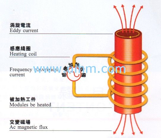
Fig. 2.2 Changein specific heat with temperaturefor materials.Source:Ref2
8 / Practical Induction Heat Treating
for various materials. Steel has the ability to absorb more heat as temperature increases. This means that more energy is required to heat steel when it is hot than when it is cold. Table 2.1 shows the difference in resistivity at room temperature between copper and steel with steel showing about ten times higher resistance than copper. At 760 °C (1400 °F) steel exhibits an increase in resistivity of about ten times larger than when at room tempera- ture. Finally, the magnetic permeability of steel is high at room temperature, but at the Curie temperature, just above 760 °C (1400 °F), steels become nonmagnetic with the effect that the permeability becomes the same as air

induction coil design

induction Principle

induction heating theory
-
Physical Characteristics:
Elementary
symbolName
Atomic weight
Specific
weightMelting point
Boiling point
Specific heat
Coefficientof
heat conductionElement
numberAg
silver
107.880
10.49
960.80
2210
0.056(0')
1.0(0'C)
47
Al
aluminum
26.97
2.699
660.2
2060
0.223
0.53
13
As
arsenic
74.91
5.73
814
610
0.082
-
33
Au
gold
197.21
9.32
1063.0
2970
0.031
0.71
79
B
boron
10.82
2.3
2300+-300
2550
0.309
-
5
Be
beryllium
9.02
1.848
1277
2770
0.52
0.038
4
Ba
barium
137.36
33.74
704+-20
1640
0.068
-
56
Bi
bismuth
209.0
9.80
271.30
1420
0.034
0.020
83
C
carbon
12.010
2.22
3700+-100
4830
0.165
0.057
6
Ca
calcium
40.8
1.55
850+-20
1440
0.149
0.30
20
Cd
cadmium
112.41
8.65
320.9
765
0.055
0.22
48
Ce
cerium
140.13
6.9
600+-50
1440
0.042
-
58
Co
cobalt
58.94
8.85
1499+-1
2900
0.099
0.165
27
Cr
chromium
52.01
77.19
1875
2500
0.11
0.16
24
Cs
cesium
132.91
1.9
28+2
690
0.052
-
55
Cu
copper
63.54
8.96
1083.0
2600
0.092
0.94
29
Fe
iron
55.85
7.896
1536.0
2740
0.11
0.18
26
Ga
gallium
69.73
5.91
29.87
2070
0.079
-
31
Ge
germanium
72.60
5.36
958+-10
2700
0.073
-
32
Hg
mercury
200.61
13.546
38.36
357
0.033
0.0201
80
In
indium
114.76
7.31
156.4
1450
0.057
0.057
49
Ir
iridium
193.1
22.5
2454+-3
5300
0.031
0.147
7
K
potassium
39.096
0.86
63.7
770
0.177
0.24
19
La
lanthaduim
138.92
6.15
826+-5
1800
0.045
-
57
Li
lithium
6.940
0.535
186+-5
1370
0.79
0.17
3
Mg
hydrogen
24.32
1.74
650+-2
1110
0.25
0.38
12
Mn
manganess
54.93
7.43
1245
2150
0.115
-
25
Mo
molybdenum
95.95
10.22
2610
3700
0.061
0.35
42
Na
sodium
22.997
0.971
92.82
892
0.295
0.32
11
Nb
niobium
92.91
8.57
2468+-10
>3300
0.065(0'C)
-
41
Ni
nickel
58.69
8.902
1453
2730
0.112
0.198
28
Os
osmium
190.2
22.5
2700+-200
5500
0.031
-
76
P
phosphorus
30.98
1.82
441
280
0.017
-
15
Pb
lead
207.21
11.36
327.4258
1740
0.031
0.08
82
Pd
palladium
106.7
12.03
1544
4000
0.058(0'C)
0.17
46
Pt
platinium
195.23
21.45
1769
4410
0.032
0.17
78
Rb
rubidium
85.48
1.53
39+-1
680
0.080
-
37
Rn
radon
102.91
12.44
1966+-3
4500
0.059
0.21
45
Ru
ruthenium
101.7
12.2
2500+-100
4900
0.057(0'C)
-
44
S
sulfer
32.066
2.07
119.0
444.6
0.175
-
16
Sb
antimony
121.76
6.62
630.5
1440
0.049
0.045
51
Se
selenium
78.96
4.81
220+-5
680
0.084
-
34
Si
selicon
28.06
2.33
1430+-20
2300
0.162(0'C)
0.20
14
Sn
tin
118.70
7.298
231.9
2270
0.054
0.16
50
Sr
strontium
87.63
2.6
770+-10
1380
0.176
-
38
Ta
tantalum
180.88
16.654
2996+-50
>4100
0.036(0'C)
0.13
73
Tc
technetium
127.61
6.235
450+-10
1390
0.047
0.014
52
Th
thorium
232.12
11.66
1750
>3000
0.126
-
22
Ti
titanium
47.90
4.507
1688+-10
>3000
0.126
-
22
Tl
thallium
204.39
11.85
300+-3
1460
0.031
0.093
81
U
uranium
238.07
19.07
1132+-5
-
0.028
0.064
92
V
vanadium
50.95
6.1
1900+25
3460
0.120
-
23
W
tungsten
183.92
19.03
3410
5930
0.032
0.48
74
Zn
zinc
65.38
7.133
419.505
906
0.0915
0.27
30
Zr
zirconium
91.22
6.489
6.489
>2900
0.066
-
40
Ohm's Law
Ohm's Law states that in a simple electrical circuit, the strength of a current (I) flowing through a resistance (R) is proportional to the applied voltage (E). It is expressed by the formula:
Thus, if you increase the voltage, and resistance remains the same, the current will increase proportionately.
Resistive Heating
Resistance is well named, for it opposes current flow. The lower the resistance, the higher the current flow in the curcuit, and hence the greater the power. This power (P) is the rate at which electrical energy is transformed into heat. It is expressed by the formula:
This heat can be put to good purpose and is the principle behind heating elements such as you will find in hair dryers and baseboard heaters. However, such direct production of heat is inefficient, localized, and difficult to control. For industrial purposes it is preferable to produce heat by using an induced current rather than a direct one.
Induction Heating
With induction heating, we substitute an induced current for a direct one, which is of course the principle of the transformer. It works this way. Alternating current flowing through the primary coils of the transformer creates an electromagnetic alternating field. Since the reverse is also true, by placing secondary coils within that field, we will induce a current to flow through them. And depending on the respective number of electrical turns in the primary and the secondary, we can step up or step down the voltage levels. It is the voltage in the secondary turns which, when applied to heating elements, creates the energy to heat or melt metals.
Resistive Heating Illustrated
Induction Heating Illustrated
Current flow is induced in the secondary circuit by placing the secondary turns within the changing magnetic field created by the primary turns.
Related Content

Type meaning of UM induction heaters

UIHM provide induction heating machines for customers from different countries

Competitive Advantages of UIHM
What is the HS code of induction heating machine
Applications of induction heating
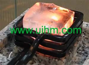
red hod ice by induction heating magic

Do you provide OEM and custom-build service?
Build induction heating brand start from energy saving


Newest Comment
i have a project of your induction heaters that we both can work out.If interested email me back at ( [email protected] or [email protected])
Regrads,
Paul.k
Post Comment