Solid State Technology of Induction Heating
2013/6/2 Views
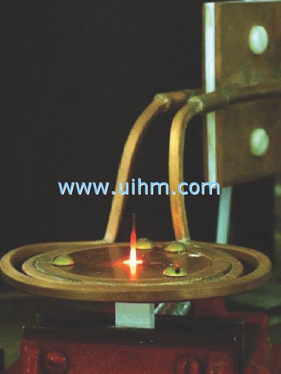
Most existing annealing systems utilize multi-turn pancake style coils and are powered by large, relatively inefficient vacuum tube power supplies. The output is often inconsistent and constant adjustments are needed to maintain product quality. The IHM series power supplies automatically tune their frequency of operation to the load during every cycle, providing optimized precision heat to every part. Digital frequency synthesis and microprocessor control deliver repeatable results, part after part, cycle after cycle. As a result, a 3kW IHM solid state power supply can often replace a much more powerful older machine, thus reducing cost.
Materials & ProcessTo selectively anneal the crimp end of the connector without affecting the receptacle end, the IHM 3H power supply is used along with a specially designed, plate concentrator induction coil. The power supply delivers 3kW at the process frequency of600kHz, providing a precise band of heat to the end of the connector. The exact process temperature will range from 900°F to 1300°F depending on the amount of annealing required. Note that the position of the connector inside the induction coil will determine the size of the annealing zone; the coil's concentrator plate should be placed just above the tip of the crimp end of the connector as shown in Figure 2. The use of fewer turns in the coil increases the operating frequency and reduces copper loss. The higher operating frequency of the power supply and coil increases the coupling efficiency of the magnetic field to the part, and increases the efficiency of the entire process. This reduces the time required to heat to the proper annealing temperature. Since copper is a very good conductor of heat, the annealing cycle needs to be fast. As shown in Figure 3, the IHM 3H power supply was programmed to maintain a total process cycle of 0.6 seconds with an annealing temperature of 1300°F. Note that the power supply requires only .02 seconds for digital tuning and that the power supply is fully on within .12 seconds from the start of the heating cycle. To rapidly dissipate heat, the
connectors should be quenched with water immediately following the heat cycle. This short heating cycle increases throughput, strictly limits the annealed area and maintains good strength associated with cold forming in the remaining section.
Conclusion
UIHM's new IHM technology has specific advantages for this type of annealing process. The high operating frequency and rapid digital tuning of the IHM 3H power supply reduce both time-to-temperature and the heating cycle, thereby improving process repeatability and increasing throughput.
Precision Induction Heating
Figure 4: Diamond tips are brazed to the corners of steel shanks for high-speed machine tools.
Brazing Small Diamond Tips On Cutting Tools Using High Frequency Solid State Power
The Problem
The operating frequency range of existing induction heating power supplies is too low for effective brazing of small parts such as diamond tips for precision cutting tools. In this section, we will show how the high frequency range of UIHM's IHM technology brings the advantages of induction heating to this type of process.
To manufacture polycrystalline diamond (PCD) and polycrystalline diamond boron nitrite (PCBN) cutting tips for high-speed machine tools, small (0.03" across) synthetic diamonds are brazed to the corners of carbide inserts or steel shanks as shown in Figure 4. The diamond acts as the cutting tip while the carbide insert or steel shank mounts to the fast- moving machine head. The braze joints are ductile, able to withstand considerable vibration and shock, and are easy to remove when the diamond tip breaks or wears in use. The brazing is done at relatively low temperatures to reduce the possibility of thermal damage to the PCD or PCBN section. A braze preform is used as the filler metal.
Manufacturers have used flame brazing for this type of process, despite its inconsistencies and limited yield, because no induction heating power supply could operate above the critical
frequency of such a small part (critical frequency is the operating frequency above which there is no cancellation of induced magnetic field inside the part; the smaller the part, the higher the critical frequency).
UIHM's new IHM technology provides high frequency coverage up to 1.2MHz to efficiently heat small parts such as diamond tips for
cutting tools with precision and advanced repeatability. Digital frequency synthesis and microprocessor control deliver repeatable results, part after part, cycle after cycle. IHM's continuous digital tuning provides more efficient heating, particularly as small parts go through Curie.
Materials & Process
The diamonds are typically 0.03" triangle- shaped and the carbide inserts or steel shanks vary greatly in size and shape. The shape of the coil along with the proper selection of the operating frequency delivers sufficient heat into the parts for this brazing application. The water-cooled coil sets up a magnetic field which induces an eddy current in the part. This eddy current flows against the resistivity of the material and produces heat. With magnetic materials, the eddy current heating is complemented by heating due to magnetic hysteresis. The induced magnetic field in the part is strongest on the surface and drops off exponentially as part depth
"Historically, the industry standard has been torch (flame) braze joints. We have used both torch and induction brazing and we are convinced that the numerous advantages offered by the UIHM IHM provide us with a superior braze joint." Michael A. Yokum, Production Supervisor Cutting Tools, CITCO Operations of Landis/Gardner
This formula dictates that for optimum heating of small parts the operating frequency of the induction equipment should be above 50kHz. However, it is important to realize that the optimum frequency for heating a part changes as the part goes through Curie. In this application, the carbide insert or steel shank becomes non-magnetic above 1370°F and looses the heating effect due to hysteresis losses. Only eddy current heating occurs above this temperature. When taking into account the overall size of the diamond tip and carbide insert or steel shank, the size and design of the coil and the resulting low coil inductance, higher operating frequencies in the 400-700kHz are required for efficient energy transfer in this process.
Precision Induction Heating
The IHM 3L was selected for this application, operating at 403kHz and programmed to produce 1400°F. The miniature diamond tips were successfully brazed to a steel shank with a ten-second heat cycle. At this rate, well over 200 parts could be brazed per hour.
Conclusion
The high operating frequency range of the IHM 3L makes it possible to use induction heating to braze very small parts such as the diamond tips required for this brazing process. Other similar manufacturing processes can also now benefit from the advantages of modern induction heating: improved repeatability, faster cycle time, pinpoint accuracy, selective heating, flexible setup and environmental cleanliness.
RS-485 Interface Simplifies Epoxy Curing With Induction Heating
The Problem
Epoxy curing in high-volume applications poses significant problems for existing heating technology. It has been difficult to maintain precise curing temperatures for several minutes and still maintain throughput. Because of the high production volumes required, a dedicated heat source for each part is not practical. Since oven heating is also often impractical because of the inefficiencies of radiant and convective heat transfer, a better solution is required for high-volume applications. The IHM 3L Power Supply with its available RS-485 interface can solve this process problem. In this section we will show how to use the standard IHM 3L with an optical pyrometer to determine precisely how much heat is required to maintain the proper curing temperature for this process.
Materials & Process
The IHM serial RS-485 interface allows the power supply to be fully controlled from a personal computer or system controller with software packages such as Procomm? or HyperTerminal?. Full operational control is available, with commands to set the voltage, control the heat, start and stop the heat cycle, and set the heat cycle timer. Full status readout is
Figure 5: The steel plug transfers its heat to the epoxy for curing.
also available by using the "READ" command. The IHM 3 responds with a data stream consisting of DC voltage, DC current, DC power, operating frequency, heat-on time, power supply status, and internal fault diagnostics. Since the data request, gathering and transmission take approximately 100ms, the full heat cycle characterization is achievable. This application involves heating a small steel plug, which in turn provides the thermal energy for curing the epoxy on the part. As shown in Figure 5, the plug is 1. 125" in diameter and rests in a Torlon plastic mold. For a complete cure, the temperature at the epoxy surface must be maintained at 400°F for six minutes. Figure 6 illustrates the tooling at the production site: a rotary table with space for 30 steel plugs placed equidistant along the
circumference. The process allows for 4 seconds of heating time per 6-minute cure cycle. The parts are loaded on the steel plugs at one station and heated to a surface temperature of450°F in 4 seconds. The IHM 3L delivers 3kW of power at 186kHz for this application. As the table rotates each plug away from the induction coil, they gradually transfer their heat to the epoxy assemblies and torlon plastic. At the end of the cycle, the parts are unloaded off of the steel plugs, and then a new heat cycle begins with fresh parts. Each steel plug retains some of its heat from one heat cycle to the next. An optical pyrometer measures the temperature of each plug just before it enters the induction heating coil. Using the RS-485 interface, a determination is made as to how much energy needs to be delivered to the plug to bring its temperature back to 450°F. The IHM 3L is instructed through the RS- 485 interface to deliver the right amount of heat for the predetermined time to each steel plug.
Conclusion
The IHM 3L's RS-485 interface connection, together with the optical pyrometer's heat measurement, enabled induction heating to be used successfully for this application. With the necessary temperature data and communications link, the power supply can precisely maintain the temperature of the steel plugs for correct curing of the epoxy.
Figure 6: The computer instructs the power supply to deliver the required energy to heat the steel plug to 450° F.
Precision Induction Heating
Small Remote Heat Station Solves RF Connector Soldering Issues On Conveyor Line
The Problem
Assembly line production of RF connectors is difficult to handle with existing induction heating systems. The flux fumes produced by the process are highly corrosive and damaging to both the power supply and its attached induction coil. Also, the high voltage requirements of most existing power supplies produce excessive arcing. In this section, we will show how a low voltage, compact remote heat station available for IHM power supplies can make the crucial difference for this induction heating process.
Materials & Process
The RF connectors produced during this process are steel cups about 1.0" in diameter and 3" long, travelling at a rate of 1800 pieces per hour on a conveyor system. As shown in Figure 7, the end cap needs to be soldered onto the can to form a hermetically-sealed connector. A solder preform is placed on thejoint area before it reaches the induction heating coil. The end of the connector is placed flush with the coil turns to ensure proper heating of the two pieces.
A good solder joint is achieved only if both pieces simultaneously reach the soldering temperature of 600°F. The solder is flux core type tin-lead wire; the flux outgasses during the heating cycle.
Selective heating is required to melt the solder onto the end cap of these connectors. Oven heating is not practical because it heats the entire connector and destroys the electronic components inside. Flame heating will not produce repeatable results. Induction heating is therefore a good heating solution for this process, but the corrosive effects of the flux and arcing tendencies of existing induction power supplies must be overcome.
To minimize arcing tendencies, UIHM's new IHM power supplies operate at lower, safer voltages than most older equipment. To remove the power supply from the conveyor line area and the corrosive effect of the solder flux, a variety of compact remote heat stations are available. The power supply can actually be located up to 200 feet away from the induction coil, depending on the application.
For this soldering application, a IHM 3L power supply produced 3kW at 250kHz. A small remote heat station and a channel-type induction coil were used to heat the top end of the RF connector and the end cap. As shown in Figure 8, corrosive flux flumes evaporate off the part and will tend to condense on any cool metal surface in the vicinity. The heat station can be located underneath the conveyor line, outside of the natural path of the flux fumes, and connected to the power supply with a flexible, low-voltage cable. A fume hog is recommended on top of the induction coil to vent the flux fumes coming off the joint area. To provide additional protection against arcing, a non- conductive sleeve is slipped over the copper coil turns.
Conclusion
IHM technology eliminates the RF connector soldering issues associated with this process. By reducing the power supply's voltage requirements and removing both the power supply and heat station from the path of the solder flux fumes, the RF connectors can be produced with high throughput and improved yield without damage to the heating components.
Figure 8: Both the low-voltage power supply and remote heat station can be located out of the path of the corrosive fluxfumes produced by this soldering application.
Next: hardening induction coilPrevious: Brazing Equipment of Diamond Tools
Down Attachment
- DownloadAttach1: Solid State Technology of Induction Heating.pdf Clicks
Good
Bad


Newest Comment
No Comment
Post Comment